2011-2016 LML EFI Live Switch Installation Instructions

This article will explain how to install your LML LSP5 switch.


This article is for the LSP5 switch installation for customers using the Spade tuner.  If you have EZLYNK hardware click here for correct installation instructions.


1. Open your hood to gain access to your engine bay and locate your hood latch grommet.LML Switch fig 1
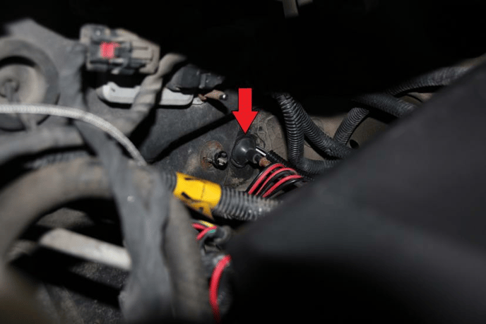
 

2. Pull the hood latch grommet out. Use 3 to 4 feet of wire as a trace wire. Feed it through the hood latch grommet on the engine bay side into the cab of your truck. 


3. Use electrical tape to secure the two LSP wires to the trace wire. Carefully pull the trace wire back through the hood latch grommet and into the engine bay. 


4. Disconnect the trace wire from the LSP switch wires. Make sure that you have enough wire through the hood latch grommet to reach the ECM and then put the hood latch grommet back in place. 


5. Locate the ECM on your vehicle. If you are standing at the driver side fender it will be down in front of the fuse box and battery.


6. Remove the ECM Shield.LML Switch fig 3.2

The ECM Shield can be removed by pinching the tab at the back of the shield and pulling towards the opposite side of the engine. 

LML Switch fig 4


7. You now have access to your ECM connectors. There are three connectors (Black J1, Blue J2,      and Grey J3). The LSP Switch will be wired into the Grey (J3) connector.

We have found it easiest to remove all three ECM harnesses starting with the one closest to the front of the truck and moving back towards the firewall. 

LML Switch fig 5


8. Each connector has a Red tab that needs to be slid out; this is the locking mechanism. 

Use a small flathead screwdriver or a 90-degree pick to slide these red locking mechanisms out. 

LML Switch fig 6


9. Push the tab on top of the ECM connector in. LML Switch fig 7

This will allow the ECM lever to be released. Push the lever back until it stops. 

LML Switch fig 8

Repeat for each connector. Disconnect all three ECM connectors.


10. In order to pull the Grey (J3) connector up high enough to disassemble it, you will need to push the connector down under the power steering line and pull it back up. LML Switch fig 9


11. Use side cutters to cut the zip tie holding the top of the ECM connector on. On each side of the Grey (J3) connector there are tabs holding the top of the ECM connector on; use a small flathead screwdriver to pop these tabs up and remove the top of the harness cover. LML Switch fig 10


12. On the bottom of the ECM Connector you need to remove the grey cover. You can do this by carefully prying on it with a small flathead screwdriver or use a pick and lift up on each corner. Be VERY careful; these pieces break easily. LML Switch fig 11

Once the bottom of the grey connector is off all of the ECM pins will be exposed. Be careful not to damage any of these. 

LML Switch fig 12

13. For 2011 to 2012 trucks which use black/yellow switches locate pin 11 and pin 48.

 LML Switch fig 13.2


For 2013 to 2016 which use blue/white switches locate pin 27 and 46.

LML Switch fig 14.2

(On some vehicles, the pinholes described above will have pins in them already. If this is the case for your vehicle, please remove the pin that is located in that pin location by carefully releasing the locking mechanism on the bottom of the pin. Once the pin is out please wrap the pin in electrical tape and place them to the side.)


14. With access to the proper pin holes, you can now slide your LSP switch pins into the proper pinholes. Pay attention to which direction the switch pin goes in. These pins are directional and will only lock if they are slid through in the correct direction.

15. Put the grey pin cover back in place. LML Switch fig 16


16. Put the black wire cover back in place. LML Switch fig 17


17. Run conduit over LSP wires and then run the grey connector back under the power steering line. 


18. Re-connect each ECM connector starting with the Grey J3 connector and working back towards the front of the truck.


19. Then mount the switch somewhere you see fit inside the cab of the truck.


To test/ verify the installation of your switch visit LSP5 Switch Testing & Trouble Shooting