Tools Required
- J 44257 Wiring Harness Connector Remover
- J 44247 Internal Wiring Harness Installer
REMOVAL
1. Caution:
Refer to Battery Disconnect Caution in Service Precautions.
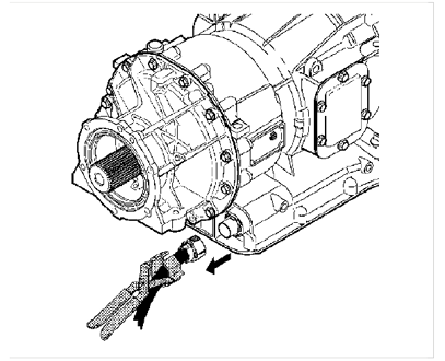
Disconnect the external wiring harness from the main transmission connector.
Use the J 44257, if the connector is not easily accessible.
2. Remove the oil pan and suction filter.
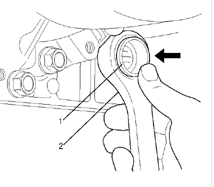
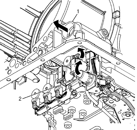
3. Important - The transmission main connector is actually one end of the internal harness that protrudes through the main housing.
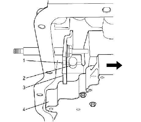
Place a 30 mm (1 3/16 inch) 12-point deep socket or box-end over the connector
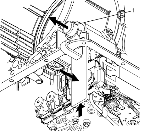
4. Push inward on the socket or wrench to release the retainer feet that attach the connector to the main housing.
5. Remove the wrench. Push inward on the electrical connector to separate it from the main housing. This allows the internal wiring harness to remain with the control valve assembly as it is removed.
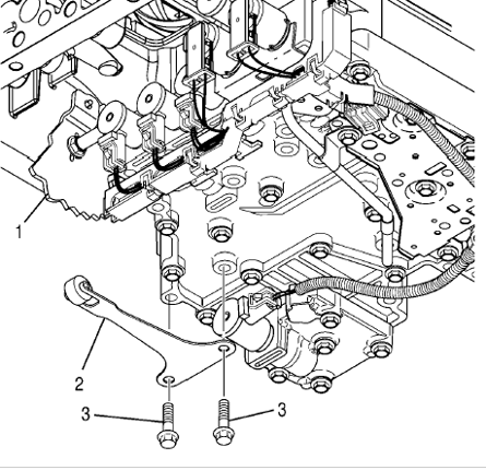
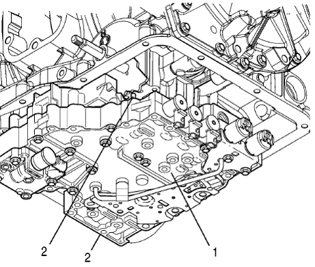
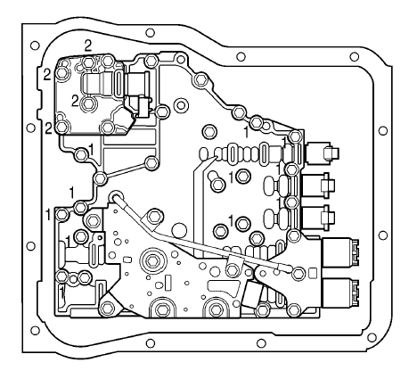
6. Remove the 2 detent spring bolts. Remove the detent spring assembly.
7. Important - As the control valve assembly is removed, be careful not to lose the manual selector valve pin or allow the manual selector valve to slide out of the control valve assembly.
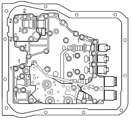
Remove 15 bolts holding the valve body in. Support the valve body assembly and remove the last bolt.
8. Lower the control valve assembly to clear the dowel pins in the main housing.
9. Move the control valve assembly sideways to disengage the pin in the manual selector valve from the slot in detent lever. Remove the control valve assembly.
INSTALLATION
1. Move the control valve assembly into position under the main housing. Engage the pin in the manual selector valve into the slot in the detent lever.
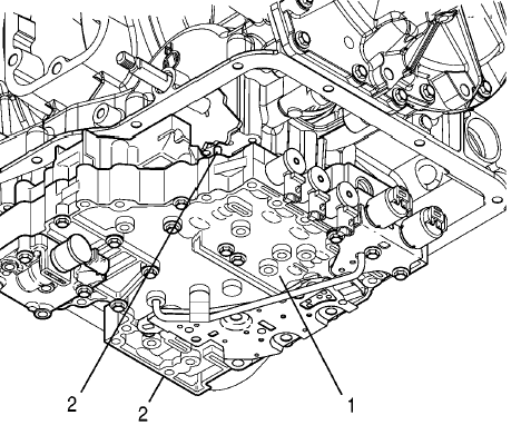
2. Align control valve assembly with the dowel pins in the main housing. Seat the control valve assembly against the main housing and hold it into position.
3. Install one bolt to hold the control valve assembly in place.
4. Reinstall the remaining bolts that fasten the control valve assembly to the main housing. tighten to 108 inch pounds.
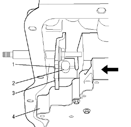
5. Push the main transmission connector outward through the hole in the main housing until the retaining feet on the connector are nearing the locked position.
6. Use the J 44247 to complete the seating of the retaining feet that lock the connector into the main housing.
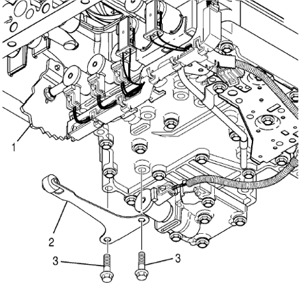
7. Install the detent spring assembly onto the control valve assembly. Confirm that the roller of the detent spring assembly rests on the detent lever.
8. Install 2 detent spring bolts and tighten to 108 inch pounds.
9. Install the oil pan and the suction filter.
10. Connect the external wiring harness to the main transmission connector.
11. Once the kit is installed we recommend changing the fluid and filters after 1000 miles of driving.
If you have any further questions or didn't find an answer to the question you had in this article, click here and fill out the form and one of our Remote Support experts will be in contact with you.